Working on a real-world Android app isn't just a matter of writing code. Most of the time you work in a team, and the code must be tested, but also well documented. Many people say that the code should be self-explanatory and you should understand how the app works just by looking at it. This isn't completely true. Sometimes you need a way to represent the architecture of your app, check dependencies between different components or see how classes are related to each other. At the same time, you need to communicate with your colleagues in an easy but very expressive way using a quick diagram on a scratch paper or on a whiteboard. But how can you do that?
In this tutorial, you'll learn everything you need to know to document your Android app using Unified Modeling Language (UML).
You'll learn:
- What UML is and how it helps you document your app.
- What you can say about your app using a deployment diagram.
- How to represent the dependencies between different components. This can help with understanding the Dagger dependency graph.
- What a class diagram is and what the main relations you can describe are.
- How to represent how different components collaborate to achieve a specific task.
- What the state of your app — or part of it — is, and how can you move from one state to another.
UML is a very big topic, but in this tutorial, you'll see just what you need for a typical Android app.
Note: This tutorial assumes you're familiar with Android development and Android Studio. If these topics are new to you, read the Beginning Android Development and Kotlin for Android tutorials first.
Getting Started
In this atypical tutorial, you won't write a single line of code, but you'll use the existing Poster Finder app.
Download the project by using the Download Materials button at the top or bottom of this tutorial. The app uses data from the Open Movie Database API website, which requires a free key and allows a maximum of 10,000 requests per day. Once you get the key, you need to add it to your local.properties file like this:
// ... omdb_api_key="INSERT_YOUR_KEY_HERE" Build and run the app, insert the text Indiana into the EditText at the top and press Enter. You'll get something like the following:
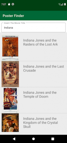
Poster Finder app
As you've probably guessed, you can use this app to search for a movie and display its poster by clicking on the image. You can play with the app and see how it works from a user's perspective. But how does it work internally? How is the code structured? That's what you'll map out using UML.
Understanding UML
You probably already know that UML is a standardized modeling language consisting of a set of diagrams. It was developed to help system and software developers specify, visualize, construct and document the components of software systems.
That's an intimidating definition, and it might make you think that to use UML you'll need some very complicated programs with expensive licenses. That's not true — or, at least, it's not true anymore.
Each UML diagram must be:
- Focused: Every UML diagram should describe just one single aspect of a system and answer a very specific question, like: What are the main packages of the app? How are they related to each other?
- Simple: You should be able to draw a UML diagram on the fly on a small piece of paper or quickly on a whiteboard. You don't need an expensive tool for this.
- Intuitive: Each UML diagram should be very easy to understand. As you'll see, UML is a typical example of the Pareto principle: With 20% of the UML standard, you cover 80% of cases. For the exceptions, you just add some notes with additional information.
- Quick: You should be able to draw a UML diagram very quickly because it should only express one thing.
- Open: You don't need to follow some strict UML convention. UML is a language that you can twist at your will as long as it helps describe a system. An example of this is the concept of stereotype you'll see later.
Although you can draw a UML diagram on a small piece of paper, in this tutorial you'll use LucidChart.com. This is an online tool for creating some basic UML diagrams with a free account. This is just one of the tools you can find online. However, you could use any other tool or, of course, a piece of paper.
Deciding What to Document
As stated earlier, each UML diagram should have a specific goal or answer a single question. You shouldn't create a diagram to explain something that's obvious.
In this tutorial, you'll use UML diagrams to answer the following questions:
- What does the Poster Finder app do?
- Who's the Poster Finder app interacting with? And how?
- What's the structure of the Poster Finder source code?
- What are the main classes and other abstractions? How are they related?
- What's a stereotype and how can it help you document your system?
- How do you describe the way different objects collaborate to achieve a given task?
- What about asynchronorus communications between objects?
- State is an important concept. How do you represent different states and the transitions between them?
UML provides the tools to answer all those questions.
Creating Use Case Diagrams
The Poster Finder app allows you to search for a movie by name and then displays its poster, if available. How can you represent the main use cases of the app with a diagram? In UML you do this using a use case diagram. That's a way to answer the following questions:
- Who can access the app?
- What can a user do with the app?
- What are the main features of the app?
Consider the following use case diagram.

Use Case Diagram
What does it tell you? It tells you that:
- You're in the context of the Poster Finder app. You represent this using a box as a boundary for the app and putting the name at the top of it.
- The Poster Finder app doesn't need any particular credentials and any user can access it. You use a stylized human symbol to represent any actor (user).
- You represent any use case with an oval containing a short description. In this diagram, any user can simply display the poster for a movie. To do this, you need to access other functionalities.
- To display the poster for a movie, you need to search for the movie title. This is another use case that you need so you include it in your use case. You represent the inclusion using the dotted line with an open arrow with the «includes» description. As you'll see later, any description between «» is called a stereotype. You do the same for the Display Movie Details use case.
This is the use case diagram for the Poster Finder app, but it's also worth giving a quick example of a more complicated case.
Creating Complex Use Case Diagrams
Suppose now that every user can search for a movie poster, but only some of them can actually display the detail. You also want to represent the case where the movie isn't found. How can you represent this in UML?
Look at the following diagram:

A Complex Use Case Diagram
A good exercise is to try to understand what this diagram is telling you just by looking at it. It tells you some important aspects:
- This app can have two different types of actors: authenticated or not. Any Android user can search for a movie, but only an authenticated user can display the poster.
- The line ending with an empty triangle represents a fundamental relation you'll see a lot in other diagrams. This is the way you represent the generalization. Here you're saying that an authenticated user IS-A Android user. In this context, IS-A means "can do the same things that". So an authenticated user can do, at least, all the things that an Android user can do.
- There are different types of use cases. Some represent the happy path, where everything goes well. However, alternative use cases describe what happens when something goes wrong. In the context of the Poster Finder app, a user might search for a movie, find it and display its poster. This is the happy path. On the other hand, it's possible that the movie isn't in the database, so the app has nothing to display. This isn't necessarily an error, but it's a use case that differs from the happy path and requires something different. In UML, you call the Not Found an extension point for the Search Movie Name use case. You represent it with an oval with a horizontal line in the middle.
- When you define the extension point, you also define the alternative use case. As you see in the diagram, you connect the alternative use case to the extension point using a dotted line with an open arrow with the «extends» stereotype. This means the Display Not Found Message use case extends the Search Movie Name use case for the Not Found extension point.
The extensive description above just proves that a picture — or in this case, diagram — is indeed worth a thousand words… or at least a couple hundred. :]
Creating a Deployment Diagram
The first question you want to answer is about the external system the app will talk to. This is the goal for the following deployment diagram.

Poster Finder Deployment Diagram
This is a very simple diagram that gives you lots of important information:
- The box symbol represents a node, which is any physical device. It could be a server machine or an Android device, like in this case.
- You use the same box symbol to represent the server. The box is empty because you don't know how the server is implemented — and you don't even care! :]
- What really matters is the interface the server exposes. You represent this with an open semicircle connected to the box that provides it.
- The semicircle representing the interface the server exposes has a label that describes what protocol — or in general, what interface — you need to access it. The Open Movie Database server exposes an API that uses JSON over HTTP.
- The lollipop matching the open semicircle represents a client for server's interface.
- The client accessing the server using the HTTP protocol is the Poster Finder app, which you represent with the symbol of a component. A component is some software that lives in a container that, in this case, is the Android environment.
- An important property of UML is its extensibility. In this case, you're adding some extra information the client needs to access a server when using the insecure HTTP protocol. You're then using a note to describe the XML document your app needs to whitelist the server.
- The dotted line with the open arrow represents a dependency relation and it's how you bind a note to its target.
It's surprising how much information you can convey with a simple deployment diagram!
Creating a Dependency Diagram
The dependency relation is one of the most important things you can represent in a UML diagram. As you already learned with the deployment diagram, you represent dependency using an open arrow with a dotted line. This is also the relation you use when representing dependencies between packages.
Open the Poster Finder project with Android Studio, and you'll get a structure like the following:

Poster Finder Code Structure
This tells you what the packages for the app are, but it doesn't tell you their relation. This is what a package diagram, also known as a dependency diagram, can tell you.
Note: It's important to clarify what dependency means. Formally, an item A depends on an item B if any change in B can cause a change in A. It's important to note how the concept of dependency is quite general and A and B can be anything. In the context of software development, these items could be classes, objects, packages, components or any other construct.

Poster Finder Package Diagram
As you can see in this diagram, you:
- Represent each package with a file cabinet symbol with the name at the top.
- Describe subpackages, putting their symbols into the symbols of the superpackages. In this diagram, all the packages are direct or indirect subpackages of com.raywenderlich.android.posterfinder.
- Use the dotted line with an open arrow to represent dependencies between packages. In the previous diagram, for instance, recyclerview and viewmodels depend on the model subpackage.
- Can also use the dependency relation in case of multiple subpackages. In this diagram, for instance, you say that all the packages in ui depend on utils.
- See how the di package depends on the main abstraction of the app, like the ones in repository, ui or conf. This is because it's where all the components are wired together.
As you learned earlier, each UML diagram should describe a single aspect of the system. This diagram describes dependencies between all the packages of the Poster Finder app. In theory, a package diagram allows you to tell more, like:
- Which components go into each package, with related visibility.
- Specific relations between packages like merge and include.
- Some of the main abstraction for each package with their relations.
Putting all this information in the same diagram would make it more complex to read and maintain. If you need to explain more, the advice is to create a new diagram. For instance, you could draw this diagram if you want to explain more about the main abstractions in the repository package.

Repository Package
With this diagram, you're saying that the repository package:
- Contains the MovieRepository interface.
- Also has the OMDbMovieRepository class that implements MovieRepository.
- Contains the OMDbPagingSource class used by OMDbMovieRepository.
Although this is a perfectly valid UML document, it doesn't give much useful information.
The use case and package UML diagrams are very important, but your apps have code you'll want to explain and document. What, then, are the main diagrams you can use?
Creating Class Diagrams
So far, you've created diagrams explaining some high-level aspects for the Poster Finder app, like:
- What the app does and who its users are.
- How the app communicates with external systems.
- What the structure of the packages and their dependencies are.
When engineers need to change the app, they need to know how the code works. They need to know what the main components are and how they're related. This also allows you to recognize design patterns — or the lack of them. When the items you need to document are classes, you create a class diagram. In this case, the main rule is still not to describe everything, but just what you need.
Open the MainActivity file in the ui.screen package and look at the following code:
@AndroidEntryPoint class MainActivity : AppCompatActivity(), NavigationHandler { private lateinit var viewBinder: ActivityMainBinding override fun onCreate(savedInstanceState: Bundle?) { super.onCreate(savedInstanceState) viewBinder = ActivityMainBinding.inflate(LayoutInflater.from(this)) setContentView(viewBinder.root) if (savedInstanceState == null) { displayFragment(MovieListFragment()) } } override fun displayFragment(frag: Fragment, backStack: String?) { supportFragmentManager.beginTransaction() .replace(viewBinder.anchorPoint.id, frag).apply { backStack?.let { addToBackStack(it) } } .commit() } } As you can see, the main items here are:
-
MainActivity -
NavigationHandler -
ActivityMainBinding
What can you say about them? Consider this class diagram:

Class Diagram for MainActivity
There are lots of things to say here:
- You represent each class with different sections of a box. In this diagram, the name MainActivity also tells you that it's a concrete class. You'll see later how to represent abstract classes. In Kotlin, you also know that a class is final by default unless you don't write otherwise. This aspect isn't important in the context of this diagram.
- The second part of
MainActivitycontains the instance variables for the class. Of course, this isn't all of them, just the ones you want to describe. In this case, you have theviewBinderproperty of typeActivityMainBinding. It's fundamental to note that the property is private. This is because you have a – in front of it. You represent public variables with + and protected with #. - The last section should contain the methods for the class. In this case, you have nothing — not because
MainActivitydoesn't have methods, but because they're not important for this diagram. You'll see cases later when putting method definitions here is useful. - You represent the
AppCompatActivitywith a simple rectangle with the name of the class in it. This is because you're not interested in the structure ofAppCompatActivitybut, as you'll see soon, in its relations with the other classes. The same is true forActivityMainBinding. -
NavigationHandleris an interface. You represent an interface with a box with two parts. The first contains the name of the interface and the stereotype «interface». In theory, you could represent an interface by writing its name in italic, but this isn't a good practice, especially if you draw the diagram on paper. - The lower part of the box for
NavigationHandlercontains the list of operations that, for an interface, are public. This is the reason for the +. In this diagram, you also see how the operation is in italic, but, as said, this isn't a must — although it might be useful in the case of some default function implementations.
This is how you can represent classes and interfaces, but there's something more important to represent: their relations.
Representing Relations
Above, you learned how to represent classes and interfaces, but what makes a class diagram useful is the way it represents relations. What's the relation between MainActivity, AppCompatActivity, ActivityMainBinding and NavigationHandler? Consider the same class diagram:

Class Diagram and Relations
In this diagram, you can see three of the most fundamental relations:
-
MainActivityextendsAppCompatActivity. The correct way to explain this is thatAppCompatActivityis an abstraction ofMainActivity, and you represent this using a solid line ending in an empty triangle. This is implementation inheritance because you're saying thatMainActivityIS-AAppCompatActivity, and so it does all the things thatAppCompatActivitydoes. In this diagram you're not saying whatMainActivitydoes in a different way fromAppCompatActivityand so you are not showing the method you override. -
MainActivityalso implements theNavigationHandlerinterface. This is interface inheritance, and you represent it using a dotted line ending with an empty triangle. With this, you're saying thatMainActivitydoes whatNavigationHandleris supposed to do. The fact thatMainActivityisn't abstract implicitly says that it provides implementation fordisplayFragment(). - The relation between
MainActivityandActivityMainBindingis a very interesting one. A very generic way to read this isMainActivityusesActivityMainBinding, but here you're saying something more. With the solid line starting with the full diamond and ending with an open arrow, you're saying that not only doesMainActivityuseActivityMainBinding, but that it also creates an instance of it. This happens throughActivityMainBinding.inflate(), but the important thing here is that the lifecycle ofActivityMainBindingis the same asMainActivity, which creates it. Also, theActivityMainBindingyou create isn't visible outside and, even more important, it's not shared with anyone. In short,MainActivityowns the instance ofActivityMainBindingit creates. The name for this relation is composition.
These are some of the most important relations you can represent in a class diagram. However, composition isn't the one you have when using dependency injection. In that case, you have aggregation.
Understanding Aggregation
As an example of aggregation, consider the following class diagram that describes what's in the repository package. It's what you can associate with the following code you find in the OMDbMovieRepository.kt file in the repository package.
class OMDbMovieRepository @Inject constructor( private val endpoint: OMDbEndpoint ) : MovieRepository { override fun getMovies(query: String): Flow<PagingData<MovieDto>> { return Pager( config = PagingConfig(pageSize = PAGE_LENGTH, enablePlaceholders = false), pagingSourceFactory = { OMDbPagingSource(endpoint, query) } ).flow } } And in the OMDbEndpoint.kt file in the api package:
interface OMDbEndpoint { @GET("?plot=full") suspend fun findMoviePoster( @Query("s") movieTitle: String, @Query("page") page: Int, @Query("apikey") apikey: String = BuildConfig.omdbApiKey, ): OMDbResponse } 
Class Diagram – Aggregation
This diagram has a few important things to note:
- As you already know,
OMDbMovieRepositoryimplementsMovieRepository. -
OMDbMovieRepositoryusesOMDbEndpointwith an aggregation relation you represent with a solid line starting with an empty diamond and ending in an open arrow. You can say thatOMDbMovieRepositoryaggregates anOMDbEndpoint. This means thatOMDbMovieRepositoryisn't responsible for the creation ofOMDbEndpoint. Somebody else is providing the referenceOMDbMovieRepositoryneeds. A consequence is that the sameOMDbEndpointcan be shared between different objects. It also means that the lifecycle of the object of typeOMDbEndpointisn't bound to the lifecycle ofOMDbMovieRepository. In this diagram, you also mention what the cardinality of the aggregation is. For eachOMDbMovieRepository, you have oneOMDbEndpointimplementation. - You learned that UML is an open language. You can use your own symbols as long as it's clear what you want to represent. In this case, you're using a custom stereotype, «Retrofit». This tells the reader that the
OMDbEndpointinterface describes an endpoint using the Retrofit framework. This is quite Android-specific, but you're expecting the reader to be an Android engineer, so that shouldn't be a problem. - Open the OMDbEndpoint.kt file in the api package, and you'll see how
operationhas the suspend modifier. But, how do you represent a suspend function in UML? This isn't something that UML provides by default. But, again, the goal is to make this clear. In the previous diagram, you just add the suspend modifier to the signature forfindMoviePoster(). Pretty simple, right? :]
As you can see, a class diagram is very simple as long as you decide to describe just a few aspects of your code.
You learned how to represent classes, interfaces and the main relations between them. But how do you represent an abstract class?
Representing Abstract Classes
To see an example of an abstract class in the Poster Finder project, open the BaseFragment.kt file in the ui.screen package and look at the following code:
abstract class BaseFragment : Fragment() { // 1 protected var navigationHandler: NavigationHandler? = null // 2 @CallSuper override fun onAttach(context: Context) { super.onAttach(context) navigationHandler = context as? NavigationHandler } } This is the base class for Fragments that want to access the NavigationHandler in the hosting Activity, if any. Note how you use:
- The abstract keyword for
BaseFragment. - The protected visibility modifier for the instance variable navigationHandler.
The following class diagram describes BaseFragment and its relation with MovieListFragment, which you find in the same package:

Abstract classes in UML
A few interesting things to note in this diagram are:
- You represent the abstract class using the «abstract» stereotype above the name of the class, that's optionally in italic.
-
navigationHandlerhas protected visibility and you represent it with the # symbol. -
MovieListFragmentis a concrete realization ofBaseFragment. As you already learned while working with interfaces, you represent this with a dotted line ending with an empty triangle.
Speaking of Fragments, here's an interesting case to consider. It's a great opportunity to learn how to represent static members in UML.
Representing Static Members in UML
When working with Fragments, it's not uncommon to see code like what you find in the DisplayPosterFragment.kt file in the ui.screen package:
@AndroidEntryPoint class DisplayPosterFragment : Fragment() { companion object { @JvmStatic private val MOVIE_KEY = "MOVIE_KEY" // 1 @JvmStatic fun create(movie: UiMovie): DisplayPosterFragment = // 2 DisplayPosterFragment().apply { this.arguments = Bundle().apply { putSerializable(MOVIE_KEY, movie) } } } // ... } In this code, you define a companion object with the:
-
MOVIE_KEYconstant to use as a key forBundlecontaining the arguments forFragment. - static factory method
create()returning theDisplayPosterFragmentgiven the model of typeUiMoviewith the data to display.
Again, how can you represent DisplayPosterFragment in UML? Consider the following diagram:

Class Diagram – DisplayPosterFragment
In this simple diagram, there are three interesting things to note:
- You say that
DisplayPosterFragmentis aFragmentusing the custom «fragment» stereotype. This allows you to save some space, avoiding the representation of the parentFragmentclass. -
MOVIE_KEYis constant and static. You understand it's a constant because it's all CAPITALIZED. You then realize that it's static because it's underlined. - The same is true for
create(). This is a static method because it's underlined.
The diagram ignores the fact you're using a companion object. This depends on the detail of the information you want to represent. If you wanted to make the companion object explicit, the diagram would be like the following:

Class Diagram – Companion Objects
Here you represent the companion object as a private static variable for DisplayPosterFragment. The relation is a composition, meaning that DisplayPosterFragment is responsible for the creation of DisplayPosterFragment.Companion. It's up to you to decide if this version gives you meaningful information.
Representing Just What You Need: Another Example
In the previous paragraphs, you saw different class diagrams and learned how to use custom stereotypes like «fragment». As said in the introduction, UML allows you to do what you think is best for improving the readability of your system. A UML diagram should be simple and small. Consider the following version of the diagram you saw earlier about MainActivity:

Class Diagram Simplified
In this diagram, you used two very useful tools to make it simpler and smaller:
- Using a lollipop notation, you're just saying that
MainActivityimplementsNavigationHandler. This is very useful if you don't care about the operation of the interface, or when you have used it more than once and you want to save space. The lollipop notation consists of a solid line ending in a circle without arrows. - You save a lot of space using the «activity» custom stereotype.
This is an example of how UML allows you to describe many things with a small diagram. Stereotypes are very useful in many cases.
Using Stereotypes
In the Poster Finder app, you have some classes apparently very similar that you can consider as Plain Old Java Object (POJO). Open the MovieDto.kt file in the api.dto package to get the following code:
data class MovieDto( @SerializedName("imdbID") val movieId: String, @SerializedName("Title") val title: String, @SerializedName("Year") val year: String, @SerializedName("Type") val type: String, @SerializedName("Poster") val posterUrl: String ) Now open the UiMovie.kt file in the ui.model package to get this:
data class UiMovie( val id: String, val title: String, val posterUrl: String, ) : Serializable The Poster Finder project doesn't have a database. Otherwise, for instance using Room, you would have something like:
@Entity data class Movie( @PrimaryKey @ColumnInfo("id") val movieId: String, @ColumnInfo("title") val title: String, @ColumnInfo("year") val year: String, @ColumnInfo("type") val type: String, @ColumnInfo("poster") val posterUrl: String ) They are all implemented with data classes, but they have different contexts. The question now is: How do you represent all these different classes? The answer is custom stereotypes, like this:

Custom Stereotypes
What do you want to communicate with this diagram? Besides the different properties, you're saying that:
-
MovieDtois a Data Transfert Object (DTO). -
UiMovierepresents an object you use for the UI and it implementsSerializable. -
Movieis an entity, so it has to do with persistence. - All the properties are read only. This is a typical use of a constraint you represent using the {constraint} symbol. What the constraint is depends on the context or, for instance, the language. In this case, this means you're using a val instead of var.
Again, it's up to you to decide if these diagrams are necessary for understanding the code in your app. In the case of the Poster Finder app, probably not. It would be much more useful to use them in a diagram representing the relations.
Creating Dynamic UML Diagrams
The diagrams you've learned about so far are static, meaning they describe unchanging relationships between different items. UML also has other types of diagrams you can define as dynamic that describe how different items collaborate or communicate over time. Two very important dynamic UML diagrams like this are:
- Collaboration diagrams
- Sequence diagrams
As its name says, a collaboration diagram describes how different objects collaborate to accomplish a given task. The goal is to understand what objects communicate most so they can be put in the right place. For instance, objects communicating very frequently will probably, but not necessarily, go in the same package. This diagram helps you to understand that.
You use a sequence diagram to describe how different objects collaborate over time. As you'll see, time is an explicit thing you represent with a vertical line.
Before describing a diagram of each type for the Poster Finder app, it's important to note how both collaboration and sequence diagrams deal with objects and not with classes. How do you represent an object, then?
Representing Objects
In the previous class diagrams, you saw how to represent a class. For instance, if you open the OMDbResponse.kt file in the api.dto package, you'll find the following code:
data class OMDbResponse( @SerializedName("totalResults") val total: Int = 0, @SerializedName("Search") val items: List<MovieDto> = emptyList(), @SerializedName("Response") val response: String = "" ) Using what you've already learned, you represent OMDbResponse with the following class diagram:

OMDbResponse
As you see, you replaced each {readonly} with a note that gives the same information without a lot of repetition. In the case of objects, you want to give different information, like:
- What are the objects' types?
- If you have multiple instances of the same type, how do you distinguish one from the other?
- If it's important, what are the values of some of the properties for that specific object?
All the objects are part of an objects diagram that is basically a snapshot of the memory of your system in a specific moment. This isn't a diagram you use very often. In the case of the OMDbResponse, you might have something like the following:

ObjectDiagram – OMDbResponse
This is the object diagram of an instance of OMDbResponse containing two instances of MovieDto. In terms of the UML notation, you see that:
- If you have only one instance of a class and you don't care what instance it is, you represent it with a rectangle with the name of the class with a : as the prefix. Basically, you use the notation :class-name.
- To distinguish different instances of the same class, use the notation instance-name:class-name. In this case, the two instances are part of the same list, so you can use the subscript notation. Again, as the name for the instances, you can use what you prefer, depending on what you want to describe.
- Sometimes it's also useful to list the values for the instance properties of interest. In this example you list the values for
movieIdandtitle.
Object diagrams allow you to put on paper a snapshot of the memory of the system you want to describe. Objects are also important to describe how different instances collaborate with each other.
Understanding Collaboration Diagrams
A collaboration diagram is a way to describe how different objects interact with each other, with an emphasis on the objects themselves. Consider the following diagram that describes the main operations in the initialization of what you see in the MovieListFragment.kt file in the ui.screen package:

Example of Interaction Diagram
This diagram is very simple and it describes part of the initialization for MovieListFragment using some symbols:
- An interaction diagram describes objects you represent with a box containing the name of the instance and the name of the class following the instance-name:class-name conventions. In this case, note how the name is underlined.
- Like for
movieAdapter, you can explicitly state the name of the instance. In other cases, you omit it because you only have one or it's simply obvious. - The diagram describes how the objects collaborate, drawing a line with a label that follows the conventions order:method-name. The order tells you when a method is invoked before or after another. The method name tells you what method an object invokes on another.
- In this diagram, note how
MovieListFragmentinvokes the static methodinflate()onFragmentMovieListBindingthat is a class. If this is important, a note makes this detail more explicit.
As said, an interaction diagram gives information about which objects interact and how. If you're interested in the time sequence of the operations, a sequence diagram is probably the best choice.
Understanding Sequence Diagrams
If you want to describe in more detail how different objects interact with each other, the sequence diagram is the right tool for you. In the following diagram, you describe the same initialization process for the RecyclerView in MovieListFragment.

SequenceDiagram MovieListFragment
Notice a few interesting things:
- You represent each object with a box containing the name in the format instance-name:class-name . Again, if the name of the instance isn't important, you can simply use the notation :class-name . Compare this with the collaboration diagram, and you can see how the name is now underlined.
- In a sequence diagram, time is important and it has a special symbol. You represent the lifetime of an object with a vertical dotted line starting from the object itself. In this diagram, the lifetime is vertical, but you could also give the same information with a horizontal line and a diagram that's basically rotated 90 degrees.
- The vertical position of each object is also important. In this diagram, the
:MovieViewModelinstance is below the:MovieListFragmentone because it is created later. The same is true for the other instances. - Objects interact, invoking methods or, in a more formal way, sending messages. You represent this using horizontal lines ending in closed arrows with a label for the method name.
- The vertical rectangles on top of some portions of the timeline are activations. They allow you to group the method invocations that are part of the same method. The one for
onCreateView()is a good example and allows you to group the invocations toFragmentMovieListBindingandRecyclerView.
In the previous sequence diagram, you only represent method invocations and consider implicitly how to return the result. This is what happens most of the time, but what about asynchronous invocation?
Understanding Asynchronous Invocations
If your app is using some sort of asynchronous APIs like LiveData or, more generally, coroutines, how can you represent your code in a sequence diagram? Open the MovieListFragment.kt file in the ui.screen package and look at the following method:
private fun search(query: String) { searchJob?.cancel() searchJob = lifecycleScope.launch { viewModel.searchMovie(query).collectLatest { movieAdapter.submitData(it) } } } How would you represent it in a sequence diagram? Consider the following diagram that represents a simplified version of the method without the cancellation:

Sequence Diagram with Async messages
This is a very interesting diagram because there are some symbols for representing asynchronous messages, but there isn't a unique way to represent them for Android. However, this sequence diagram has many interesting things to note.
- You have four different instances at the higher level of the diagram: :MovieListFragment , lifecycleScope:LifecycleCoroutineScope , :MovieViewModel and :MovieAdapter . This tells you that, in the context of the description of what happens in
search(), they already exist. - This diagram describes what happens when some client invoked
search(). This triggers thelaunch()message onlifecycleScope. It's important to note here that thelaunch()message is synchronous and you use a closed arrow at the end of the horizontal line. - The previous note isn't true for the
searchMovie()message on:MovieViewModel. This happens in the scope of the coroutine and you can represent it as an asynchronous message using a horizontal line ending in an open arrow. -
searchMovie()creates and returns aFlow<PagingData<UiMovie>>. In this diagram, you make the return type explicit using a horizontal dotted line, from right to left, ending in an open arrow. This is how you represent return values in a sequence diagram. - In this diagram, you also see an activation symbol close to another. When you send the
launch()message, you're also passing a lambda that you can represent using the second activation symbol. - The last thing to note is the cross symbol that represents the end of the life of a particular instance. In this case, you represent the end of
Flow<PagingData<UiMovie>>.
This diagram is also an example of how important it is to focus on a single detail of the code you want to describe. This way, you can avoid the creation of overly complex and large diagrams.
Understanding State Diagrams
The state is a fundamental concept in modern Android development. You can define a state as a set of values an item has in a specific instant. A typical example in Android is about Activity that can be in different states that define the activity lifecycle. The Lifecycle Architecture Component defines the states you can find in the following state diagram:

State Diagram – Lifecycle Component
This is a very simple state diagram that contains some of the main symbols you can use:
- The full circle represents the initial state. This is the state of your item when it starts to exist. As you see in the diagram, once you exit that state, you never return.
- Your system remains in the same state until "something happens", and then it moves to another state, represented by a rectangle with rounded corners and its name inside.
- As you learned, the system moves from one state to another when "something happens". This could be anything, like the invocation of a method or some asynchronous operation. In the diagram, the transition from CREATED to STARTED happens when the ON_CREATE happens.
- In a state diagram, you represent the final state with a circle with a smaller full black circle inside. As the name says, this is the final state, and you cannot exit from it.
There are other things you can represent in a state diagram and it's worth having a quick look.
Diving Deeper Into State Diagrams
To learn more conventions about state diagrams, look at the following one:

State Diagram with Conditions
This diagram contains two more pieces of information. In it, you:
- Represent a state with a round-cornered box split into two parts. The upper contains the name of the state. The lower contains the action that the system does while in that state. For instance, the system displays a spinner while in the Loading state.
- Know that you can move from one state to another when "something happens". Most of the time, it's because of a message or method invocation with a condition that you represent with [condition]. This means that the transition happens if the event happens and the [condition] is true.
State diagrams are one of the most useful UML diagrams you can use, but, as always, be careful to focus on a single aspect of the system you're describing.
Where to Go From Here?
Great job completing the tutorial! You learned how to create the most important UML diagrams for documenting your app. It's fundamental to understand that UML is a language you can modify however you want, just as long as it's easy to understand. Very complicated diagrams with a lot of symbols and details generally do more harm than good and introduce confusion rather than clarity.
You can checkout this dedicated UML website to learn more about UML.
We hope you enjoyed this tutorial! If you have any comments or questions, feel free to join the discussion below.
raywenderlich.com Weekly
The raywenderlich.com newsletter is the easiest way to stay up-to-date on everything you need to know as a mobile developer.
Get a weekly digest of our tutorials and courses, and receive a free in-depth email course as a bonus!
Source: https://www.raywenderlich.com/21792733-uml-for-android-engineers
Posted by: mazychanelayes.blogspot.com
